Supported Devices
| Device Type | Modbus TCP (Ethernet) | RS485 |
|---|---|---|
| ABB B21 | ❌ | ✅ |
| ABB B23 | ||
| ABB B24 |
Wiring
RS485
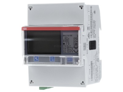
The ABB B-series meters (B21, B23, B24) use a 3-pole RS485 connection. Connect these to the ControllerDemoName as follows, based on the meter's terminal markings.
1. Device (ABB Meter) Pinout
This table shows the terminals on the meter itself.
| Signal | Terminal Number |
|---|---|
| A | 37 |
| B | 36 |
| C (GND) | 35 |
IMPORTANT: Troubleshooting
The 'A' and 'B' labels are not universally standardized. If the ControllerDemoName cannot find the device during a scan, it is often due to a wiring mismatch.
Swap the A and B wires (between the controller and the meter) and try scanning again.
2. Controller & Converter Pinout
This table shows the corresponding RS485 pins on DemoBrandName controllers and converters. Match the 'A' and 'B' from the meter (see table above) to the 'A' and 'B' on your controller.
| Device | SmartgridOne Controller model OM1 | SmartgridOne Controller model IG8 | RS485-USB converter | RS485-Ethernet converter |
|---|---|---|---|---|
| A | RS485 A | RS485_POS | RS485 A | TX+ |
| B | RS485 B | RS485_NEG | RS485 B | TX- |
| C (GND) | RS GND | GND | Not available | G |
Configuration
- You MUST give each device on the RS485 bus a unique address. Check the manual of the device on how to do this.
- Use lower addresses first (1, 2, ...) because the DemoBrandName ControllerDemoName will find them faster!
- For each device, it is generally recommended to stick with the factory default baud rate, parity, and stop bits. The DemoBrandName ControllerDemoName will scan on those first.
Use the following Modbus settings in the ControllerDemoName's device wizard. These are the default settings for the meter:
- Baudrate: 19200
- Modbus Address: 1 (or the address set on the meter)
- Parity: Even
- Stop bits: 2