Cadis water meter
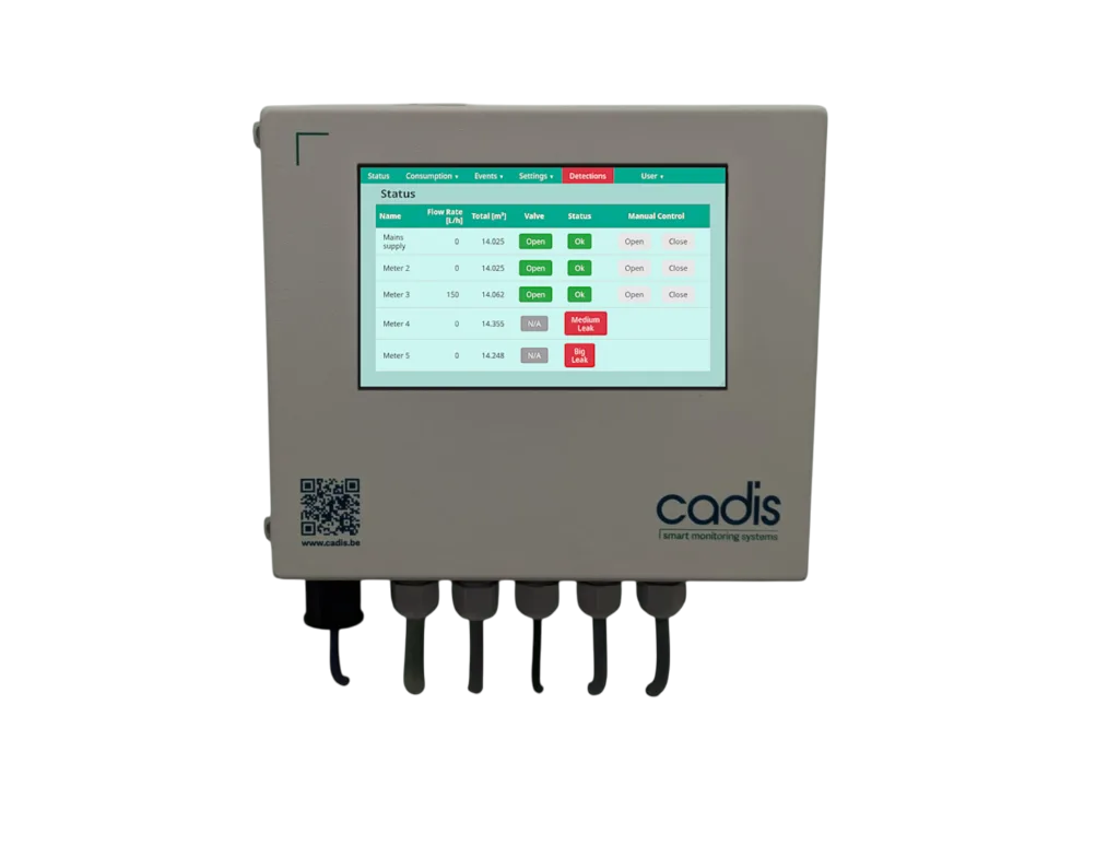
The Cadis AQUAVISION CONTROL is a module for monitoring and leak detection. It is designed to connect to water meters that have a pulse output and can control motorized shut-off valves to automatically stop water supply in case of a large leak. The module can monitor up to 5 pipes and control up to 3 automatic shut-off valves.
The module can transmit data to a Building Management System (BMS) via Modbus TCP/IP over a computer network or via a Modbus RTU (RS485) connection.
Supported Devices
| Device Type | Variants | Modbus TCP (Ethernet) | RS485 | Curtailment |
|---|---|---|---|---|
| AQUAVISION CONTROL Module | Monitors up to 5 water meters and 3 valves | ✅ | ✅ | ✅ |
Wiring
The DemoBrandName ControllerDemoName can communicate with the AQUAVISION CONTROL module via either Ethernet (Modbus TCP) or RS485 (Modbus RTU).
Ethernet (Modbus TCP)
Connect a standard RJ45 network cable from your network switch to the dedicated network port. This port is located on the bottom left side of the module housing.
For correct ethernet wiring, follow the guidelines for ethernet wiring.
RS485 (Modbus RTU)
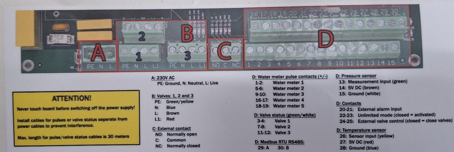
If a network connection is not possible, wire the RS485 A/B lines from the DemoBrandName ControllerDemoName to the terminals on the module's main board. The connection terminals are D29 for Modbus A and D30 for Modbus B.
- For correct RS485 wiring: Follow the guidelines for RS485 wiring.
- If the wiring shown in the table below is incorrect, please let us know.
- There is no general consensus in the industry about the usage of A and B for the RS485 polarity, so it may be counterintuitive and opposite of what you might expect for some devices.
| Device | DemoBrandName ControllerDemoName model OM1 | DemoBrandName ControllerDemoName model IG8 | RS485-USB converter | RS485-Ethernet converter |
|---|---|---|---|---|
| Pin 29 (Modbus A) | RS485 A | RS485_POS | RS485 A | TX+ |
| Pin 30 (Modbus B) | RS485 B | RS485_NEG | RS485 B | TX- |
| N/A | RS GND | GND | Not available | G |
Configuration
Modbus RTU
Configuration for Modbus RTU is straightforward as the main parameter is fixed:
- Modbus Address: The Modbus slave address is fixed at 1 and cannot be changed.
Based on the driver, the recommended serial settings are:
- Baud Rate: 19200
- Parity: None or Even
- Data Bits: 8
- Stop Bits: 1
- You MUST give each device on the RS485 bus a unique address. Check the manual of the device on how to do this.
- Use lower addresses first (1, 2, ...) because the DemoBrandName ControllerDemoName will find them faster!
- For each device, it is generally recommended to stick with the factory default baud rate, parity, and stop bits. The DemoBrandName ControllerDemoName will scan on those first.
Modbus TCP
For Modbus TCP communication, the module must be connected to the local computer network. The module's IP address and network settings must be configured via its touchscreen to match your network.
Water Meter Setup (Required)
For the module to register consumption correctly, you must configure the pulse ratio (K-value) for each connected water meter.
- This value represents the liters of water per pulse.
- The recommended K-value for a connected water meter is between 1 and 10 liters per pulse.
- This value must be entered during the module's startup configuration.
You must not connect a second readout system (like a BMS) in parallel to the same water meter pulse output. If this is required, a pulse splitter (e.g., Cadis ref. CA-PULSE-SPL) must be installed first.