Installation of the hardware
During the installation process you must at all times take the provisions of the safety, maintenance and legal notices into account.
Model OM1
Hardware Installation
Wall-mounted
-
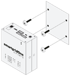
Accurately measure the hole pattern for the mounting points.
tipThe DemoBrandName ControllerDemoName has a hole pattern of 80mm x 63mm (W x H).
The screw head should not exceed a diameter of 7mm (e.g., a universal screw of 4 x 40mm is recommended).
For a flush mount, ensure the screws protrude no more than 8mm from the wall. -
Insert the required screws into the surface where the DemoBrandName ControllerDemoName will be mounted, ensuring they are securely fastened.
-
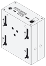
Carefully align the DemoBrandName ControllerDemoName with the installed screws and slide it into place. Ensure it is securely mounted.
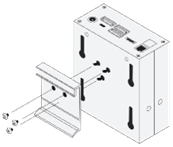
DIN-rail mount
-
Attach the DIN-rail mount to the DemoBrandName ControllerDemoName using the provided screw holes.
-
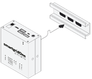
Carefully attach the DemoBrandName ControllerDemoName to the DIN-rail. Ensure it is securely mounted.
noteDIN-rail mounts need to be ordered seperately.
Electrical Installation
Power Supply
The DemoBrandName ControllerDemoName requires a 12V (2A) DC power supply connected via a 5.5mm jack. The required power adapter is included in the delivery package.
Connecting the interfaces
See the supported device guides and the wiring & connectivity guidelines for the connection of devices.
Network Connection
The DemoBrandName ControllerDemoName must always be connected to a wired (RJ45) network interface to ensure reliable communication and functionality. See also the wiring & connectivity guidelines.