
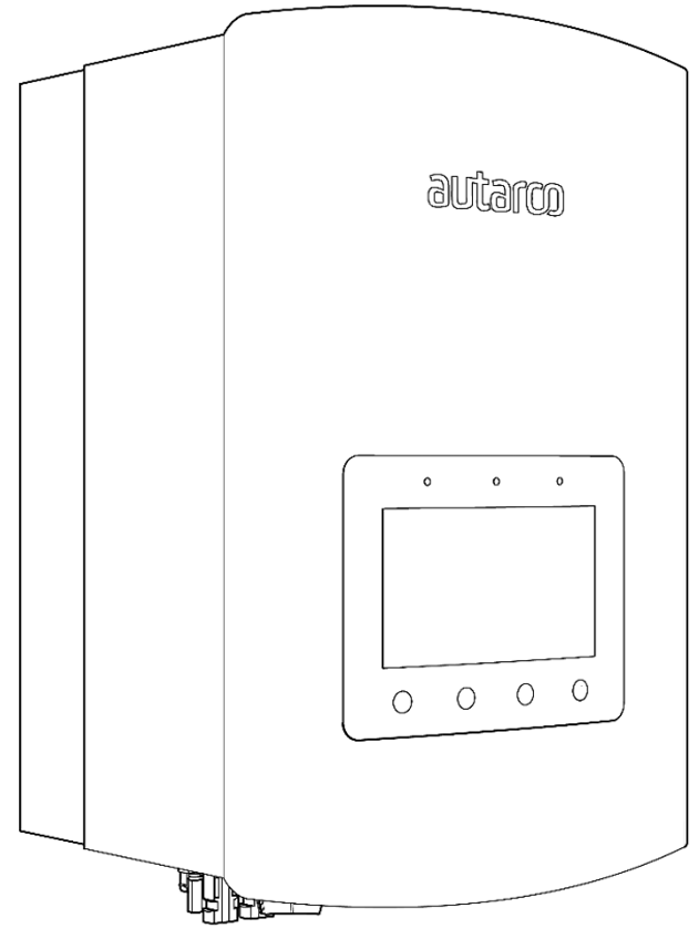
This page describes the communication with an Autarco LH-series hybrid inverter over Modbus-RTU (rs485). By default, the inverter is set to address 1. The RS485 interface is a 4-pin connector called "COM" located on the bottom of the inverter behind a protective plate. The exact position is marked in the orange box in the image below:
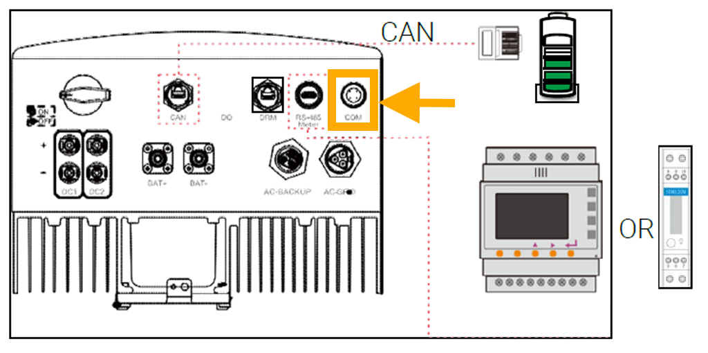
Looking closer the port looks like this:
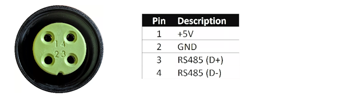
An appropriate connector should be used for this 4-pin connector on the Autarco inverter to connect to the SmartgridOne Controller. On the SmartgridOne Controller, the inverter can be connected to the RS485 port. The wiring is as follows:
Info
RS485 Wiring
- For correct RS485 wiring: Follow the guidelines for RS485 wiring.
- If the wiring shown in the table below is incorrect, please let us know.
- There is no general consensus in the industry about the usage of A and B for the RS485 polarity, so it may be counterintuitive and opposite of what you might expect for some devices.
| Device | SmartgridOne Controller model OM1 | SmartgridOne Controller model IG8 | RS485-USB converter | RS485-Ethernet converter |
|---|---|---|---|---|
| Pin 3 | RS485 A | RS485_POS | RS485 A | TX+ |
| Pin 4 | RS485 B | RS485_NEG | RS485 B | TX- |
| N/A | RS GND | GND | Not available | G |
Warning
NOTE: RS485 Device Addresses
- You MUST give each device on the RS485 bus a unique address. Check the manual of the device on how to do this.
- Use lower addresses first (1, 2, ...) because the SmartgridOne Controller will find them faster!
- For each device, it is generally recommended to stick with the factory default baud rate, parity, and stop bits. The SmartgridOne Controller will scan on those first.
Last updated December 10, 2025Edit this page